ON-LINE
MANUAL
Pneumatic Requirements
Air Consumption
and Air Compressors
The air consumption,
especially the average air consumption, of a vibrator system is the
basis for calculating the size of the air compressor needed.
In the following
table the air consumption in liters per minute for 2 and 6 bar air operating
pressure are given. The values may vary about 10 % due manufacturing
tolerances.
Fig. 2.1. Air consumption
[liters per minute] of the Powtek vibrators
| Type |
30
PSI |
90 PSI |
* |
Type |
30 PSI |
90 PSI |
* |
Type |
30 PSI |
90 PSI |
| K-8 |
83 |
195 |
* |
R-50 |
100 |
195 |
* |
DAR-2 |
70 |
200 |
| K-10 |
92 |
200 |
* |
R-65 |
200 |
400 |
* |
DAR-3 |
100 |
300 |
| K-13 |
94 |
225 |
* |
R-80 |
290 |
570 |
* |
DAR-4 |
120 |
360 |
| K-16 |
122 |
280 |
* |
R-100 |
370 |
730 |
* |
DAR-5 |
130 |
390 |
| K-20 |
130 |
340 |
* |
R-120 |
500 |
970 |
* |
DAR-6 |
170 |
470 |
| K-25 |
160 |
425 |
* |
. |
. |
. |
* |
DAR-7 |
180 |
500 |
| K-30 |
215 |
570 |
* |
. |
. |
. |
* |
. |
. |
. |
| K-36 |
260 |
675 |
* |
. |
. |
. |
* |
. |
. |
. |
.
| Type |
30
PSI |
90 PSI |
* |
Type |
30
PSI |
90 PSI |
* |
Type |
30
PSI |
90 PSI |
| GT-4/6 |
33 |
83 |
* |
T-50-LP |
70 |
165 |
* |
FP-12-S |
1 |
25 |
| GT-8/10 |
46 |
112 |
* |
T-50-HP |
80 |
190 |
* |
FP-12-M |
1 |
20 |
| GT-13/16 |
120 |
390 |
* |
T-65-LP |
90 |
240 |
* |
FP-12-L |
1 |
20 |
| GT-20/25 |
185 |
455 |
* |
T-65-HP |
110 |
290 |
* |
FP-18-S |
5 |
57 |
| GT-30/36 |
330 |
745 |
* |
T-80-LP |
150 |
290 |
* |
FP-18-M |
4 |
25 |
| GT-40/48 |
425 |
970 |
* |
T-80-HP |
150 |
390 |
* |
FP-18-L |
5 |
46 |
| . |
. |
. |
* |
T-100-HP |
200 |
390 |
* |
FP-25-S |
13 |
93 |
| . |
. |
. |
. |
. |
. |
. |
. |
FP-25-M |
23 |
87 |
| . |
. |
. |
. |
. |
. |
. |
. |
FP-25-L |
18 |
93 |
| . |
. |
. |
. |
. |
. |
. |
. |
FP-35-S |
23 |
162 |
| . |
. |
. |
. |
. |
. |
. |
. |
FP-35-M |
24 |
141 |
| . |
. |
. |
. |
. |
. |
. |
. |
FP-35-L |
38 |
135 |
2.1.1. Calculation
of the average air consumption
FORMULAS |
1. Air Consumption according to table 2.1. : CONS. = ...... liters
/ minute |
|
2. Operating Factor (On/Off) x 100% : OPF = ...... % |
|
3. Average Air Consumption = CONS x OPF : ACON = ...... liters /
minute |
|
4. Total Average Consumption = ACON x NUMBER OF UNITS DRIVEN |
To get the average
consumption of several vibrators and/or other air consumers connected
to the same supply pipe, multiply the Average Air Consumption by the
number of units if the air consumption is the same. If the air comsumption
is not the same, do the calculation for every consumer separately and
add the results.
To determine the
size of the air compressor required it is recommended to add about 20
% as a safety figure to the above calculated demand since the values
given may vary. Also, leaks or additional installations may require
a larger compressor. Extra power for future installations may also be
necessary.
To define the air
compressor size required another figure is necessary. It is the highest
consumption at any given time. This figure can be estimated taking the
air consumption of all units that may be in operation at the same time
and the length of this period :
Highest Air Consumption
=Number of units x CONS for .... minutes
= ............
liters / minute during ....... minutes
Both the volume
of the highest air consumption as well as the average consumption of
the system should be used to determine the proper compressor.
Lubrication
Dry or not dry
? This is an important question. Generally speaking, lubrication always
increases the lifetime of moving parts since it significantly reduces
friction. But, lubricating ball vibrators is a waste of lubricants because
it will not visibly increase the vibrator’s lifetime whereas dry
running T-turbine ball bearings will fail quickly.
Thanks to special
material and treatments (teflon-coating, etc.) the operating friction
can be minimized so that piston vibrators (FP-series) and DAR-vibrators
alike have very good emergency running properties. Still, after time,
lubrication becomes necessary to avoid increased abrasion..
The question of
how many drops of oil per minute are sufficient or how many are too
much cannot be answered in general. It is possible that a reciprocating
or piston air compressor supplies sufficient oil in the air so that
the use of a lubricator is not necessary. Unfortunately, the same compressor
type may supply too much machinery oil if the leakage is too great which
causes the DAR-series to decrease in frequency and force due to oil
gumming. On the other hand, air compressors with built-in air dryers
require a line lubricator to keep T-turbine, DAR- and FP-vibrators from
wearing out quickly.
IMPORTANT: For lubrication
of Powtek vibrators use oil with the viscosity:
ISO VG 5 with 5cSt/40°C (5 centistokes or approx. 42.4 Susec or
5 cm2 sec2 )
The oil needs to
be non gumming. Some examples are listed below :
- Shell Tellus
Oil C5
- Esso Nuto H5
- Mobil Velocite
No.4
- BP Energol HP
5
- For food applications
: Mobil Whiterex 304 (vegetable base)
NOTE: Oil with
viscosity other than recommended will reduce frequency and power! For
FP-piston vibrators only, distilled water may be used instead of oil
with the same lubrication effect. Adjust the lubricator to 10 drops
per minute at minimum.
As line oilers,
"drip feed" lubricators provide better results than "wick
oilers". Check the silencer for oil trace and adjust the lubricator
for minimal, but not completely without, trace. Too much lubrication
will lead pistons and rollers to clog and should therefore be avoided.
Air Filters
and Pressure Regulators
All air compressors
are equipped with air filters to protect the compressor valves. This
compressed air is clean enough to be used in all of our rotative vibrators.
Small dirt particles will be blown through, but we strongly recommend
the use of an air line filter of 5 micrometers or less. This will help
to prolong the lifetime of the vibrator.
NOTE: For FP-piston
vibrators the use of 5 micrometer filters is strongly recommended due
to the small tolerance between piston and bore.
The air filter
must be installed close to the vibrator to avoid rust particles from
iron pipes reaching vibrator. It is advisable to connect the filter,
air pressure regulator and lubricator in line as shown.
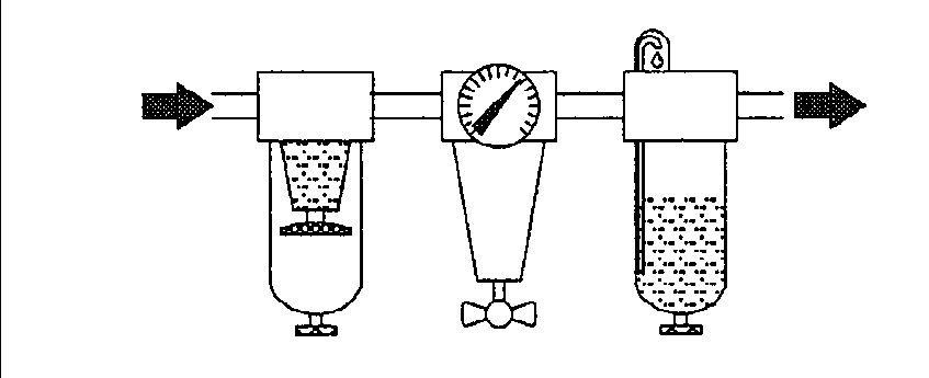 |
Correct
installation : filter, then regulator and lubricator.
|
Air Pressure
Pipes
It is of course
possible to adjust the vibrator by decreasing or increasing the air
pressure or the air volume. However the supply and the exhaust-pipes
have to be dimensioned correctly. If the ratio of these tubes is too
small, the vibrator will not be able to run at full power.
The exhaust pipe
should be as short as possible because the volume of the exhausted air
(expanded) is many times greater than the pressure difference.
The respective
formula is V(in) x P(in) = V(out) x P(out) where P is the absolute pressure
and not only the overpressure. Therefore, it can be shown easily that
when running a vibrator at 6 bar (overpressure) the exhaust air volume
is 6 times the air pressure inlet volume.
An exhaust pipe
that is too long or too short will hinder the air movemnt in such a
way that all of the air pressure cannot be transformed in the vibrator
into vibrating energy.
Using the silencer
mounted directly onto the vibrator is the best way to gain as much power
as possible. Since the question of correct pipe diameter is of importance,
the above graph can be used to determine the required value.
| EXAMPLE |
The air consumption
is 900 liters per minute at 4 bar pressure.
The pipe length is 10 meters.
So start at the right side with 900 to the left until 4 bar line.
Now follow 45° up until the break line. Then go straight to
the left until 10 meter line, then 45° up to the right until
the desired line of maximum pressure loss allowed in the system.
The inner diameter and the area can be seen at the left now. |
NOTE: The pressure
loss in the pipe should not be more than 0.5 bar; however, it does not
make sense to minimize this value too much since this will increase
the size and the cost of the pipes required. A value between 0.1 and
0.5 bar will be OK.
The required size
of the exhaust pipes can be determined the same way. Use the vibrator
inlet pressure nomogram lines but instead of inlet pressure use exhaust
pressure that is about 0.2 to 0.5 bar.
Air Valves
and Pressure Regulators
Pressure
regulators
With the help of
a pressure regulator (a needle valve, for example), the vibrator can
be adjusted to its best working conditions. The adjustable flow volume
influences vibration frequency and energy.
We recommend installing
the pressure regulator between air filter and lubricator to get best
results.
Air valves
For some applications
like emptying bins and hoppers it is advisable to use the vibrator intermittently.
To do so you may place a solenoid valve after the lubricator. Do not
put the solenoid valve in line before the regulator and lubricator because
then the regulator has to upstart every time and the air pressure is
not available immediately. This could cause the vibrator to malfunction.
It also is recommended that you place the valve as close as possible
to the vibrator.
NOTE: Do
not place supporting devices such as air filters, pressure regulators,
lubricators, etc. on a vibrating mount. This will cause devices to malfunction.
CAUTION: Make sure the inner width of the valve is large enough. (See Nomogram
to determine diameter and area of air pipes.) Otherwise, the vibrator
will not run at full vibrating energy, and piston vibrators eventually
experience difficulty starting properly.
It is also possible
that piston vibrators will not start when the valve is manually driven
because for a proper start the piston needs to be supplied with full
pressure right from the beginning. When manually driven try to open
the valve as quickly as possible or make use of solenoid valves.